
YouTube
bilibli
https://www.bilibili.com/video/BV1vGRnYoEjn
https://www.bilibili.com/video/BV1nZfHYSEMK/
https://www.bilibili.com/video/BV1CYREYvEag/
Basic
illustrate:
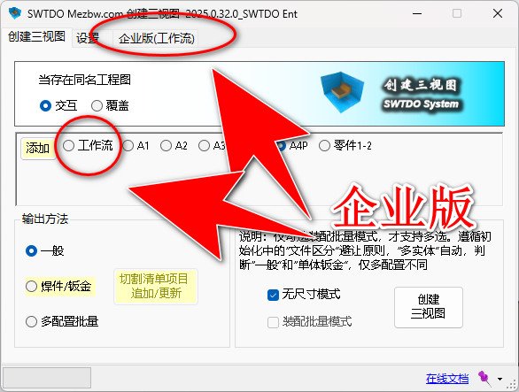
- Multi-selection support: Multi-selection is only supported when the assembly batch mode is selected and three-view creation is enabled.
- Important! Supports multiple selections in the cutting list under a part.
- File differentiation and avoidance: Avoidance
Steps to Add Template
step:
- Rename: Select any standard engineering drawing and modify it to your desired template name, such as A2-BOM.SLDDRW (A1, A2, A3, A4, A4P, and Workflow are prohibited). System usage.
- In the three-view creation process, click “Add” and select A2-BOM.SLDDRW (this process will save an Excel file).
- Open the part or assembly template, such as:
File deployment path:\SWTDODT\Document templates\Part.PRTDOT
File deployment path:\SWTDODT\Document templates\Assembly.ASMDOT - Launch the Property Manager and run it on the part template:
- Clear all properties
- Import the Excel file and add properties
Precautions
- Verify the validity of the engineering drawing: Please close all open SW files, and only open A2-BOM.SLDDRW. The content should be free of defects.
- File deployment path: \SWTDODT\Document templates\Part.PRTDOT, filename and path must not be changed.
- This process does not address drawing standards. For template-based drafting, this process is sufficient.
- A purely custom template cannot guarantee the full functionality of SWTDO, such as attribute formatting and the Prod system; however, if the drawing is created and modified based on the default SWTDO template, all functions will be available.
Learn More About Template Settings
https://www.bilibili.com/video/BV1Kp4y1A7TC
Create 3 Views vs View Annotation
1. Create three-view diagrams, automatically dimension parts, and perform passive annotation based on the sketch dimensions drawn by the user on the digital model;
2. Create three-view diagrams for entity diagrams with multiple entities: the first diagram is based on the dimensions of the user model and is passively annotated; the others are actively annotated based on the annotations of the views
3. For assembly, only the external dimensions are to be provided.
4. View annotation, based on active annotation, can be applied to components without SW features, such as STEP conversion, reference, mirroring, etc
5. Create three-dimensional views, based on BOM settings, cutting list settings, multiple entity types, sheet metal types, etc., with up to 20 or more variations;
One-sentence understanding: View annotation is only necessary when creating three-view drawings is not feasible due to size constraints
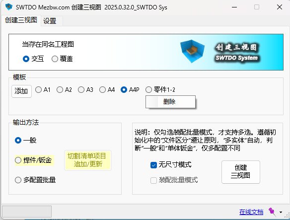
Output Method Explanation
- Batch output of multiple entities:
The output will generate an engineering drawing in a single-file, multi-sheet format (which will include at least two sheets). The first sheet will be named after the configuration, while the other sheets will be named after the cutting list items. The cutting list sheet will be attached with cutting list attribute information. If the “Expand” option is checked, the sheet metal entity will add an expanded view. All views will be annotated with dimensions and automatically adjusted for spacing and position. - general
The drawing is named “Configuration Name”, and the drawing file name is the same as the part name - Multi configuration batch output
The drawing name is the configuration name. How many configurations are there and how many drawings are generated? Note that it is a single file and multiple drawings; SWTDO only has digital to analog output and entity list, supports single file output of multiple files, limited to digital to analog. In any case, we follow the one-to-one principle, which is a mandatory rule for BOM indexing. - Single entity sheet metal
Attach sheet metal annotation file, attach expansion diagram
Two Methods of Auto Dimensioning
For multi-entity, TDO engineering drawings, the output is a single file with multiple sheets. We used two methods for annotation.
The first drawing (the initial drawing, typically the post-weld drawing) is annotated passively, based on the designer’s design intent. The dimensions in the drawing can reflect how the numerical model is drawn, which is related to the processing design benchmark. For first-class drawings, there are specific considerations for how the dimension benchmark is set
If the following images continue to use this method, the situation similar to the one shown in the preceding image will occur, resulting in part dimensions unrelated to the actual entity. This is quite foolish
So for the following figures, we’ll replace it with active annotation, which has nothing to do with how you draw the numerical simulation.
Combination Techniques
CreateView3 + batch specify fixed surfaces of sheet metal
CreateView3 + Bodylist’s properties wri
Create view3 drawings + drawing standards
Create view3 drawing + replace with drawing frame
Create three-view drawings + annotation
创建三视图+切割清单
Cut List Update / Append - This Tool Is Extremely Valuable!!
This tool, based on the already created three-view drawing, is designed for weldments where the user has manually selected cutting list items (multiple selections are supported)
Based on the existing three-view drawings, entity drawings will be added or replaced, with a strict logic for renaming and additional changes. The workload compressed by this tool is enormous, especially for steel structures and large-scale cutting lists
BOM Template and Cut List Table Template
不支持路径变更,必须存储于SWTDODT默认文件夹
But the file name can be modified or added
Default Position of BOM Table and Cut List Table
During batch processing, if the BOM or Cutlist table appears in a location that does not match the default template location, please learn the method of preset anchor points in the template on your own.
In layman’s terms, for engineering drawing templates, when editing the drawing format, find a point, right-click and set it as a BOM positioning point. The default BOM positioning point in the SWTDO template is the upper right corner of the drawing frame, and the preset positioning point for the Cutlist is the upper right corner of the title block
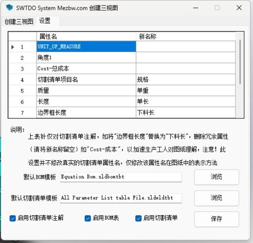
Settings - Cut List Property Table Settings
This table is for the purpose of annotating the cutting list in solid drawings
Can replace textual expressions and delete unnecessary annotation items
This table does not modify the actual cutting list attribute names, only adjusts the presentation in the drawing.
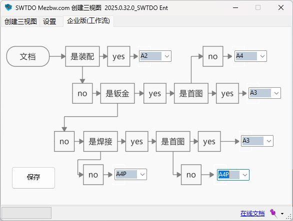
Enterprise Edition Dedicated Workflow
Controlled by SWTDO Enterprise Edition’s workflow module C-end, all U-ends use drawing templates
Under the workflow, the system will automatically determine the type of drawing based on preset settings, adjust the drawing template, and dynamically change the output results
contrast:
Personal version, only a unique image frame can be applied for each batch processing.
Workflow: Automatically adapt to preset drawing frames, modify according to attributes, and output images such as sales drawings and business drawings. Due to the significant differences in content between business drawings and production drawings, the display content is different


