
bilibli
https://www.bilibili.com/video/BV1KwyQYzEbX/
https://www.bilibili.com/video/BV1axyfYTErE/
https://www.bilibili.com/video/BV11eanzaEi7/
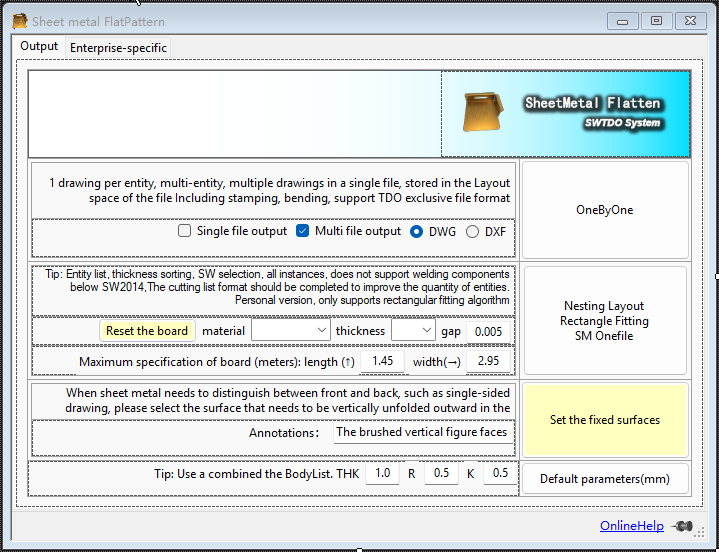
SM Onefile
- Multiple selection support: Assembly multiple selection
- Document differentiation and avoidance: No avoidance
- Supports custom cutting gap
- Supports custom board sizes
SM Onefile is used for sheet metal layout and can directly merge the unfolded drawings of all sheet metal entities in a complete assembly into a single engineering drawing.
Key scenarios:
This tool can not only run in assembly mode, but also supports use in batch processing. That is, this tool can perform unified sheet metal output for more than one set of equipment according to batch requirements.
Combo attacks:
Select SM in the entity list – All Instances + SM Onefile
The entity list attribute statistics table supports selecting all instances based on fields. All instances equals the quantity within a product set. SM Onefile can automatically layout all instances (not just parts, but sheet metal entities within parts) based on the number of parts.
SM Onefile Combo Technique
- The entity list attribute statistics table supports selecting all instances based on fields. All instances equals the quantity within a product set. SM Onefile can automatically format all instances based on part quantity.
- Sort by thickness and select multiple options to achieve layout with the same thickness.
- Multiple selections based on material sorting allow for layout of materials within the same category.
- Within the entity list, sort by material, bending radius, and thickness, and batch adjust the K-factor to achieve batch modification of sheet metal parts unfolding and resetting of layout.
SM Onefile mixed
Scenario examples:
Scenario examples:
Excerpt from a Q&A session with an AI assistant:
1. Increased complexity in production management: All parts are cut together → After cutting, sorting is required. Sorting errors can lead to missing parts in assembly and rework. More precise labeling (engraving, tagging) and logistics management are needed. Example: Side panels, door panels, and back panels for 10 cabinet sets are all cut from the same piece of material → After cutting, a pile of parts is stacked together; how do you know which piece belongs to which set?
2. Warehousing and Logistics Pressure:
Inability to “produce materials according to orders” → Inability to cut and assemble simultaneously.
Bending/assembly can only begin after all cutting and sorting are completed.
Increased Work-in-Process (WIP) inventory.
3. Reduced Production Flexibility:
If a customer cancels a set at the last minute → but the boards have already been cut and mixed → material waste or adjustments are needed.
Inability to flexibly handle order insertions and changes.
4. Difficulty in Quality Traceability:
Poor cutting quality of a single board → affects multiple cabinets.
When batch defects occur, it is difficult to pinpoint which batch/set is affected.
5. Process Constraints Limit Layout Efficiency:
In practice, part orientation, tab positions, cutting paths, and surplus material utilization all affect utilization rates. Theoretically, 1.7 boards might only be achievable through actual mixed layout (due to geometric limitations).
6. Equipment and Labor Coordination Costs:
Although layout is “free,” process engineers need to spend time reviewing and adjusting the automatic layout results.
Operators need to handle part identification and flow more carefully.
One by one
One drawing per entity; for multiple entities, multiple drawings per single file, stored in the file’s layout space; includes stamping and bending; supports TDO standard plus sign CNV file format, i.e., supports Prod indexing.
Default parameters
illustrate:
Adjust the default values for sheet metal: bending radius, sheet metal thickness, and k-factor.
Fixed surface batch specification
- Multiple selection support: Under assembly, multiple selection of “faces” is supported.
- File differentiation and avoidance: Avoidance
- Combination technique: After specifying fixed surfaces in batches, using the “Create Three Views” function will automatically reflect the information of the top surfaces in the engineering drawing.
When the front and back surfaces of a sheet metal piece have different textures (such as painted, brushed, or polished surfaces), and the sheet metal cutting direction needs to be clearly defined, this command can be used to strictly define the direction of the brushed surface.
This command adds a special attribute called “Top Face Mark” to the part. The attribute value is defined by the user.
Key scenarios:
This tool can not only run in assembly mode, but also supports use in batch processing. That is, this tool can perform unified sheet metal output for more than one set of equipment according to batch requirements.
Area Statistics [Enterprise Edition]
- Multiple selection support: Under assembly and parts, multiple selection of “faces” is supported.
- Document differentiation and avoidance: No avoidance
Used for silkscreen area statistics in conjunction with the enterprise version of the sheet metal quotation system.
It can be used under assemblies or under parts; do not use it under both parts and assemblies simultaneously, as this will cause data overlap.


